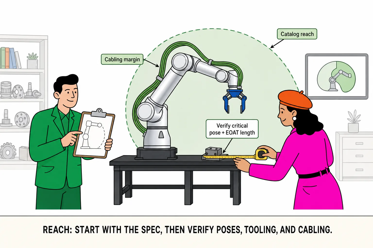
In reach selection, the line we hear most is: “The spec sheet says it’s enough—we should be fine.” Catalog reach is a manufacturer reference measured under stated install and test conditions. It answers how far the arm is rated to extend—not whether your station is covered in the pose you actually run.
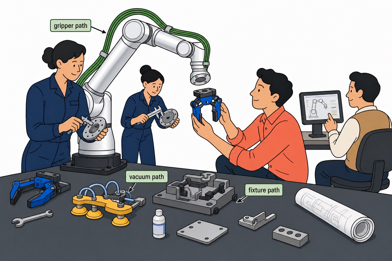
What you validate on the floor is different: your target is at the TCP (tool center point), not the flange; fixtures, grippers, and adapters add length (EOAT); pick/place angles rarely keep the wrist in a straight line (critical pose); external cable dress, guards, and neighboring equipment can burn margin before the arm hits its mechanical limit. A straight-line distance that “matches” catalog reach can still fail during commissioning.
A better workflow is two steps: use catalog reach to shortlist two or three models, then check the worst pick/place beat in your cell—stable reach, no interference, and a retract path that actually works. Do not treat “sum of link lengths” as reach. That is a sketch for explanation, not the manufacturer’s spec method, and it does not replace layout validation.
Catalog reach vs what you can actually use
Catalog reach: first-pass filter in the directory—values such as 622 mm, 922 mm, or 1402 mm—to rule out models that are clearly too short
Usable envelope: what your cell can repeat after EOAT length, approach angles, obstacles, and cabling margin are accounted for
Small example: why a far conveyor station looks “just enough” on paper
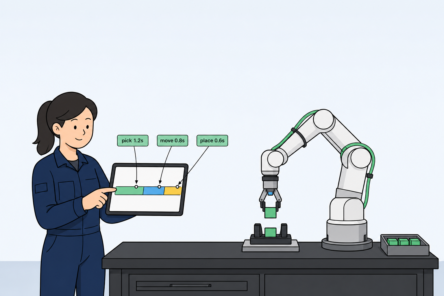
A station center sits about 820 mm from the base. A 922 mm model in the comparison table seems to leave ~100 mm of margin. But the gripper and vacuum stack add roughly 110 mm at the TCP; this station needs a side approach, so the wrist cannot stay fully extended; at full stretch the external cable bundle still needs bend clearance. Combined, effective coverage at the farthest beat can be well short of 922 mm. The right question is not “is the catalog number big?” but “do we still have margin in the critical pose?”
Common mistakes
Measuring base-to-station center only—EOAT and TCP offset missing
Assuming “if the arm can extend there, the job works”—real pick angle and retract path never checked
Leaving guards, posts, and neighboring equipment out of the layout—reach is fine, the path is not
How to verify (no fancy formula required)
Note catalog reach from the spec sheet and shortlist models
On a station sketch or CAD, mark the TCP target, EOAT envelope, and the pick/place pose that eats the most space (critical pose); measure base reference to TCP, not flange only
Walk the full in/out path (approach, retract, clearance) and confirm cables or guards are not the first thing to hit at full extension
Lock the design with critical poses inside the envelope; pilot on the floor when unsure—do not ship on “should be fine”
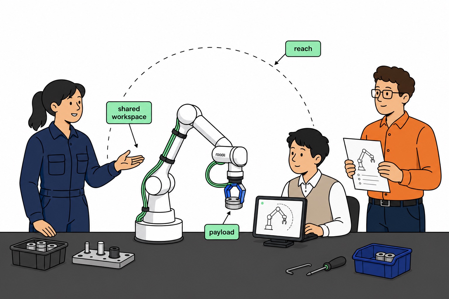
Pair reach with payload
Reach and payload are two sides of the same cell: reach covers critical poses, payload covers worst-case load. Put both conclusions in one comparison table so procurement, integration, and the floor share one link—not three versions of the story. If you are already working through payload, read the companion guide: Payload guide