PCB assembly runs—red glue, underfill, sealants, thermal interface—look like “draw a line,” but they drive overflow rework, bead width consistency, cured strength, and line balance. Manual dispense drifts across shifts, operators, and material lots; an extra 0.5 mm beside a keep-out can trigger AOI or a full wash. More EMS and board shops add collaborative arms on fixed-path, stable-material stations—not to delete process engineers, but to turn teachable beads into stored parameters you can tune, audit, and sample.
What a collaborative PCB dispense cell actually does
Typical loop:
Load board — PCB nests on fixture; datum edges/pins set plane height and XY
Dispense — taught path with pressure/speed/valve timing; corners often need slow-down or dwell
End bead — lift, cut-off, anti-tail settings (material-specific)
Cure and flow — oven/UV or rack time; the real bottleneck is often cure, not arm motion
You automate bead geometry + dispense timing—not “instant next operation.”
What you usually gain on the floor
More consistent volume and width. A 12 mm run speeds up by hand late in shift; corners pile material. Same pressure/speed on a saved path makes caliper or gravimetric sampling meaningful.
Less material waste. Overflow, tails, and touch-up map directly to glue cost—especially TIM and underfill. Automation may not cut headcount first; less glue and less wash pays on many lines before labor math.
Operators step back from mist and solvents. The arm holds the repeat pass; people own monitor, nozzle change, and board load—EHS and retention sometimes beat takt as the project driver.
SKU change adjusts recipes, not the whole line. One station, many saved paths; new board tweaks program, nozzle, and one bead-width check—commoner than hard automation per part number.
Process first: material, then path
Material and cure window decide automation scope. Fast-cure grades punish timing; odd glue points may stay manual in v1. List which beads are 100% teachable vs human touch-up—do not assume the whole board goes to the arm.
Process parameters matter more than payload.
| Parameter | Floor meaning |
|---|---|
| Pressure / flow | Primary knobs for width/height; re-verify on new lots |
| Path speed | Corner pile-up; too slow may start skin-over |
| Dwell / valve timing | Start/stop tails; pairs with Z lift |
| Nozzle / standoff | Gap to board drives bead shape; fixture height tolerance in scope |
| Cure time | Sets real takt and WIP—not arm cycle alone |
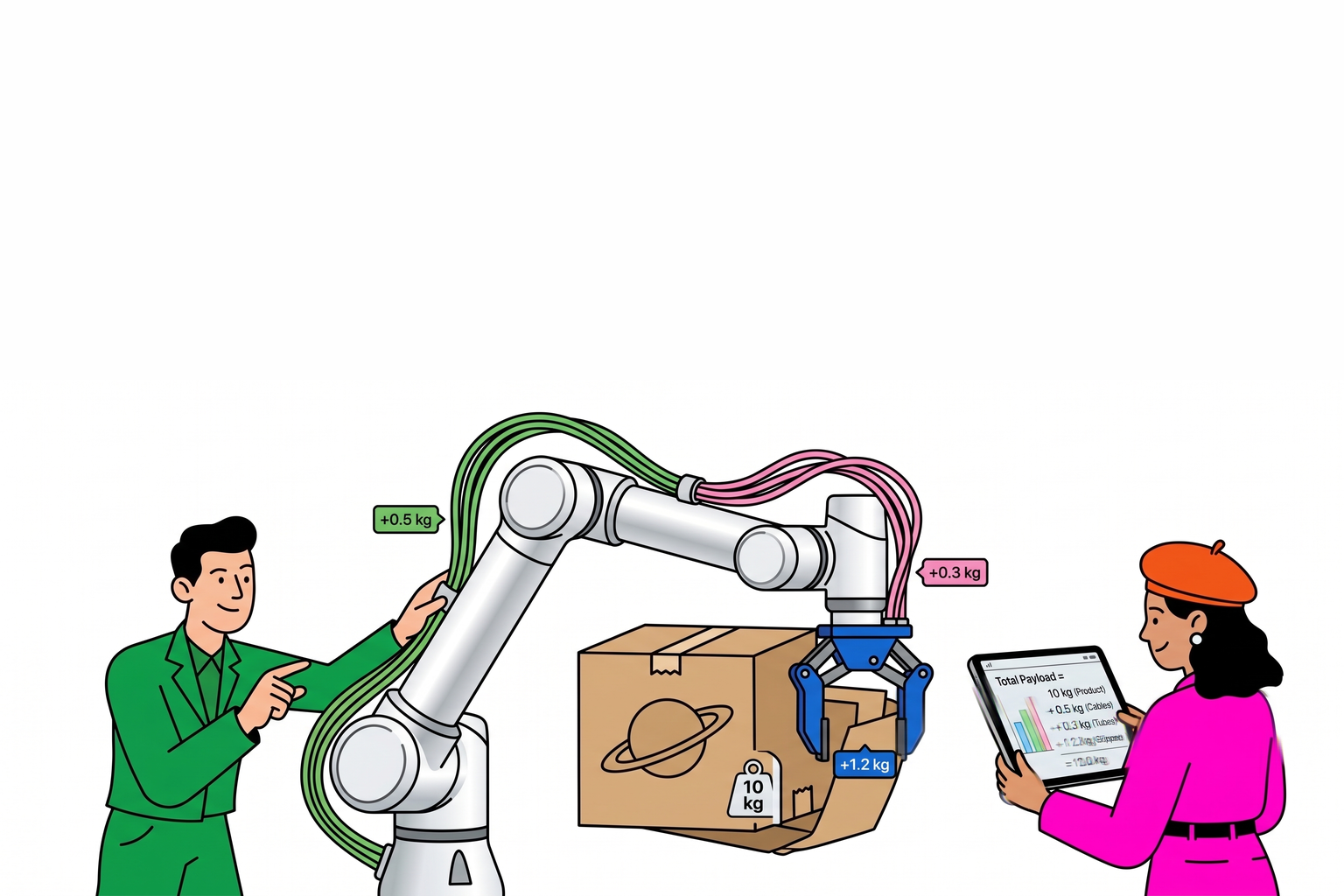
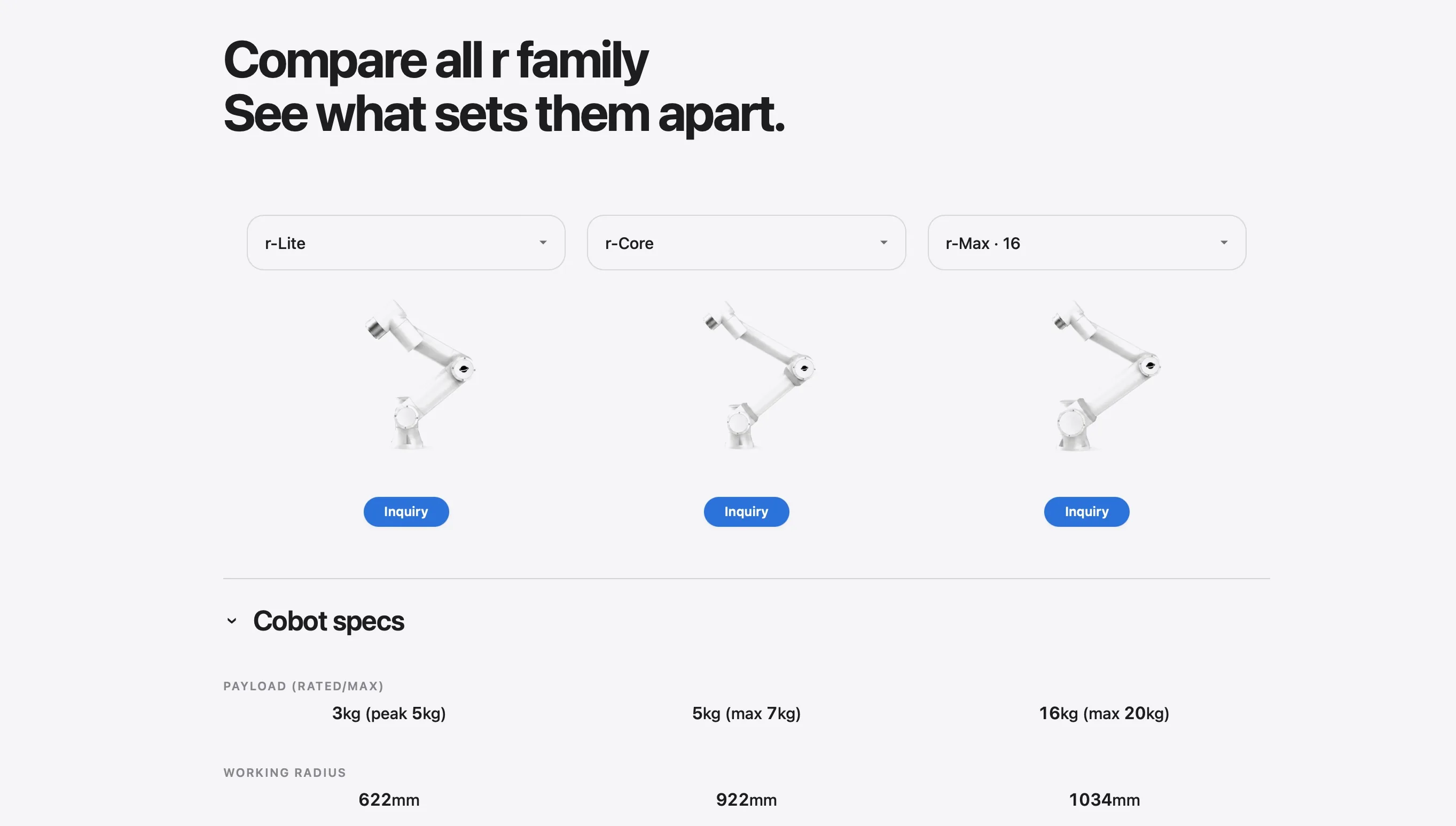
Payload is almost never the sizing story. Valve + needle + small reservoir often lands 0.5–2 kg—tight lines often start on r-Lite (~3 kg rated), then compare r-Core if you need more envelope. Review board Z repeatability, keep-out clearance, nozzle service access. Layout: Workcell layout guide.
Define acceptance before PO. Caliper samples, gravimetric checks, AOI bead rules, or destructive shear—customer standards decide vision; do not add “100% vision” after signature.
Two floor vignettes (illustrative)
Vignette A — straight or segmented beads, flat board: program + sampling. 40 mm TIM strip, target width 1.2 ±0.2 mm, first-article weigh after lot change—value is shift drift removal, not record takt.
Vignette B — odd points and dense keep-outs: split the job. Automate 80% of length; humans touch exceptions—commoner and easier to pass process review than forced “zero human glue.”
When to stay manual or buy dedicated equipment
Every board varies glue type/point layout—no recipe stability
Sub-millisecond multi-valve timing needs dedicated dispense platform
Board height tolerance exceeds nozzle standoff and fixture budget is zero
Contract mandates closed-loop vision you did not scope in v1
Integrator review checklist (PCB dispense)
| Check | What it tells you |
|---|---|
| Material, lot, cure conditions | Parameter window |
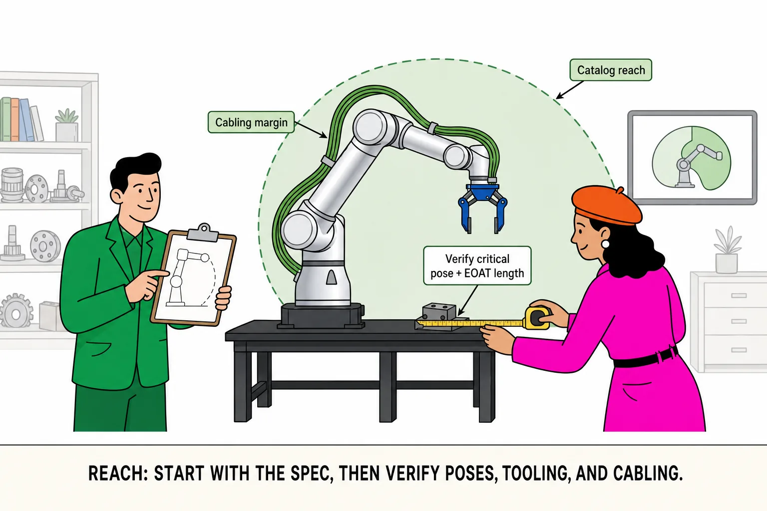
| Board Z and datum repeatability | Fails before reach |
| Speed / pressure / dwell recipes | First article and lot change |
| Tail and corner strategy | Start/stop geometry |
| Sample or AOI standard | Acceptance language |
| Human touch-up list | Scope control |